Tratamiento de imágenes ráster
Salvar a ráster
First of all, load the cartography you need to make a clipping onto a gvSIG view. Select the “Save as raster” tool which appears in the tool bar.

Now select two points in the view to define the rectangle that will contain the area to be saved. The following dialogue box then appears. If the rectangle you have marked is too small, this box will not appear and you will have to select a larger rectangle.
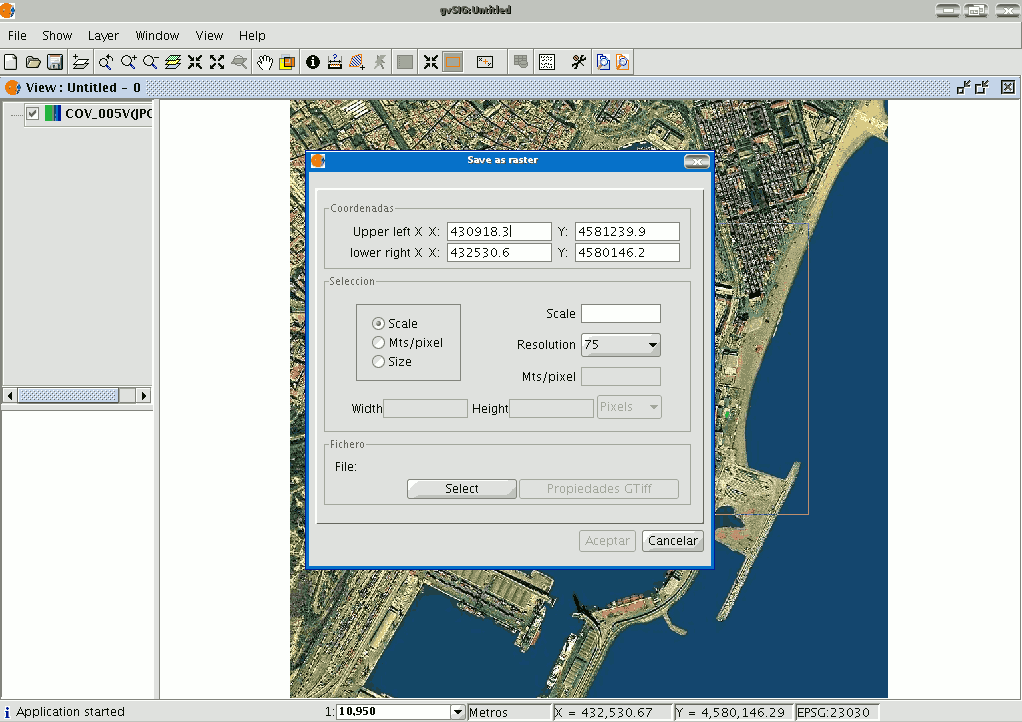
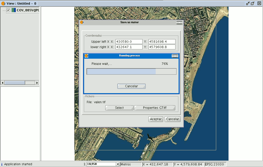
The coordinates of the points which delimit the selected area in the view appear at the top of the “Save as raster” dialogue. These coordinates can be changed manually.
The “Selection” area appears in the centre of the dialogue.
This includes three selection methods:
Scale. If you select “Scale”, the “Scale” text box and the “Resolution” pull-down menu are enabled. The pull-down menu values correspond to the points per inch in the exported image.
Input a value for the scale and press “Enter”. The Mts/pixel values and the “Width” and “Height” size of the output image are recalculated.
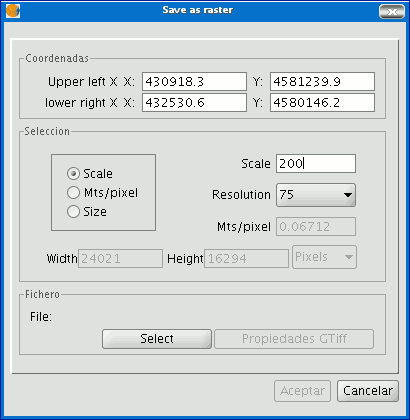
Mts/pixel: If you select “Mts/pixel” from the three radio-buttons column, the text box to input this value will be enabled. Input a Mts/pixel value and press “Enter”. The “Scale” value and the size (“Width” and “Height”) of the output image will automatically be recalculated.
Size: If you select “Size”, the text box to input the “Width” and “Height” values will be enabled. When you input one of these values, the other will be recalculated automatically to maintain the height/width proportions.
The remaining data (“Mts/pixel” and “Scale”) will also be recalculated automatically. You can also select the unit of measurement you wish to see the values in via the “Pixels” pull down menu.
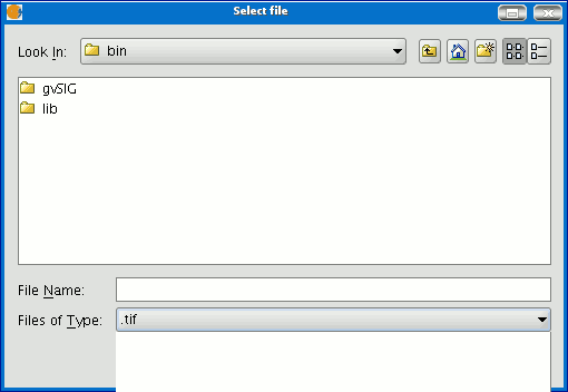
Click on the “Select” button to choose where you wish to save the image.
The most suitable driver will be loaded according to the type of file you choose (N.B. watch how the button to the right of “Select” changes), i.e. when a .jp2 output file is selected for example, you can open the properties box which corresponds to a Jpeg2000 format.
The formats available to save a file are geoTiff, jpg (georreferenced with a worldFile) and jpeg2000.
An ecw extension can be selected exceptionally and only with Linux kernel 2.4.
When you select the output file the properties button is enabled.
For geoTiff files, a box similar to the one below appears:
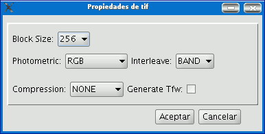
Block size: The block size defines the amount of data read each time so it can be compressed. The greater the block size the faster the compression speed but more memory is used.
Photometric: [MINISBLACK | MINISWHITE | RGB | CMYK | YCBCR | CIELAB | ICCLAB | ITULAB].
This assigns the photometric interpretation.
This is RGB by default, because the input image has 3 byte-type bands. Interleaving: [BAND | PIXEL]. The tiff files have band interleaving. Some applications only support pixel level interleaving. In these cases, this option can be modified. Compression: [LZW | PACKBITS | DEFLATE | NONE] This assigns the compression to be used. The default option is none.
A table like this will be obtained for jpg.
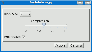
Block size: The block size defines the amount of data read each time so it can be compressed. The greater the block size the faster the compression speed but more memory is used.
Compression: This allows the image’s compression level to be adjusted.
Progressive: This allows you to make progressive jpgs.
When the image has been selected and the properties have been adjusted, click on “Ok”. A progress bar appears.
This process may take an extremely long time depending on the size of the output image.
It can take from a few seconds to several days. Thus, it is advisable to control the size of the output image via the number of pixels so we are not taken by surprise.
When the process finishes, a statistics table indicates the saved image path, the disk size of the output image, the length of the process and whether the image has been compressed or not.
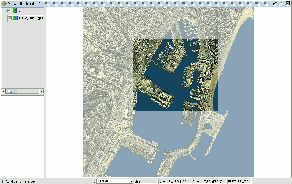
To check that the georeferencing has been correctly carried out, you can load the image you have saved as another layer and apply a transparency.
Georeferenciación con cartografía base y puntos de control
Introducción
The gvSIG programme allows an image to be georeferenced (.jpg, .tif, .gif, .png) using control points on a georeferenced base map. Firstly, the georeferenced base map needs to be loaded (in raster or vector format or both) to a gvSIG view.
Secondly, the image to be georeferenced must be added. You can load this image by going to the “Add layer” tool and selecting the “Georeference” tab. Use the “Load” button to access the image you wish to georeference.
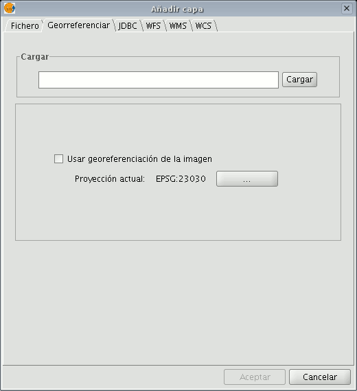
If you enable the “Use image georeferencing” check box and the image is georeferenced, it will be added to the view with its current georeference. If it is not, the image will be loaded in the centre of the view. You will then find a browser button which can be used to select the map projection.

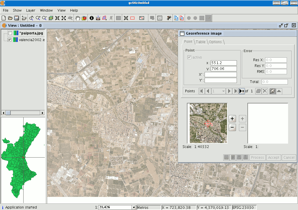
When you have finished the process, click on “Ok”. The image to be georeferenced will appear in the view and will have an asterisk “*” in the ToC to indicate that this is the layer the process is being carried out on. A new window will also appear to carry out the georeference process but first, the image to be georeferenced will have to be moved closer to the base map’s reference zone so that you can select the control points more quickly.
Aproximación de la imagen a georeferenciar
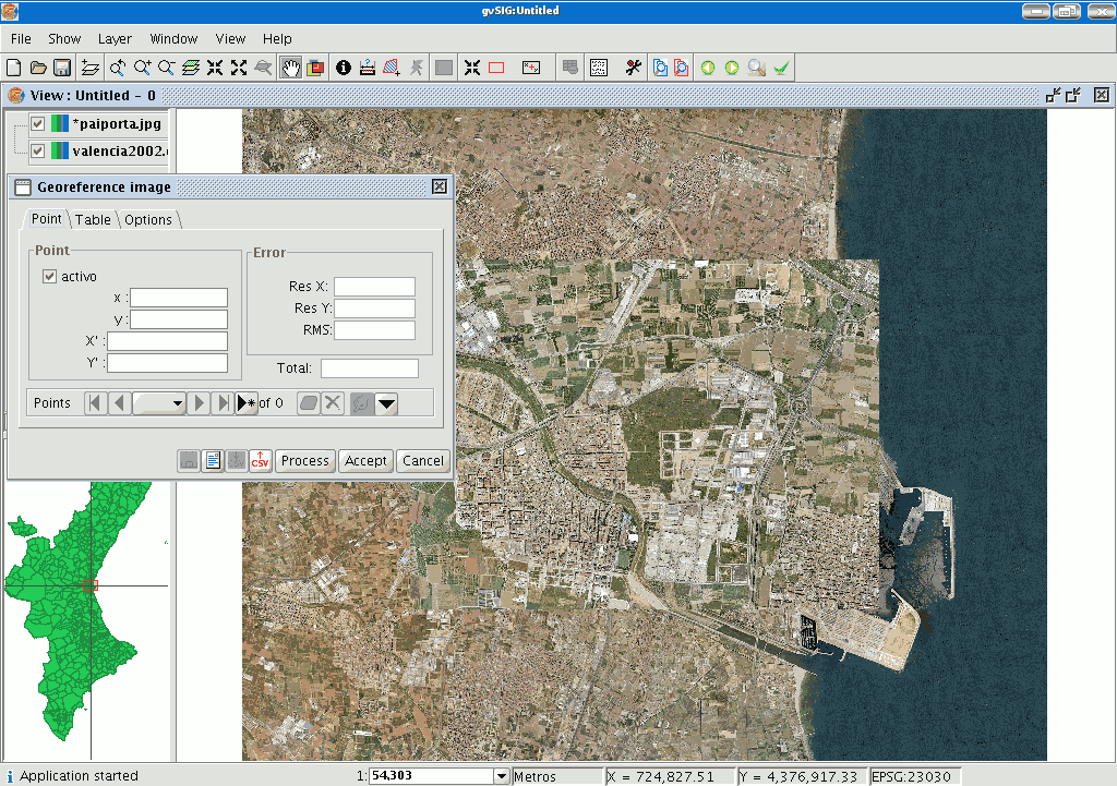
If the layer to be georeferenced is selected in the ToC, four new buttons will appear in the tool bar.
This button resizes the image to be georeferenced.

The image size can be modified and brought closer to the base map scale.

Select this tool and go to the image to be georeferenced.
A frame will be created around the image. If you place the cursor on one of the image sides, it will turn into a double arrow. This will then allow you to modify the frame size by moving the cursor.
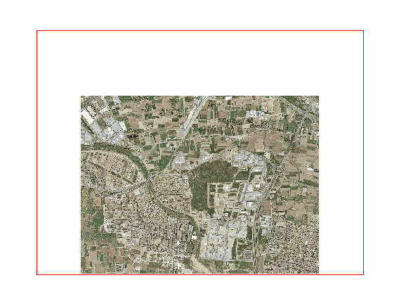
The newly created frame boundaries will become the new reference size for the image being georeferenced.

This tool allows you to move the image to be georeferenced around the view and thus bring it closer to the reference base map.

This tool takes you back to the previous position of the image to be georeferenced in the view.

This tool is activated when the previous tool has been used and allows you to redo what you have previously undone.
Selección de puntos de control
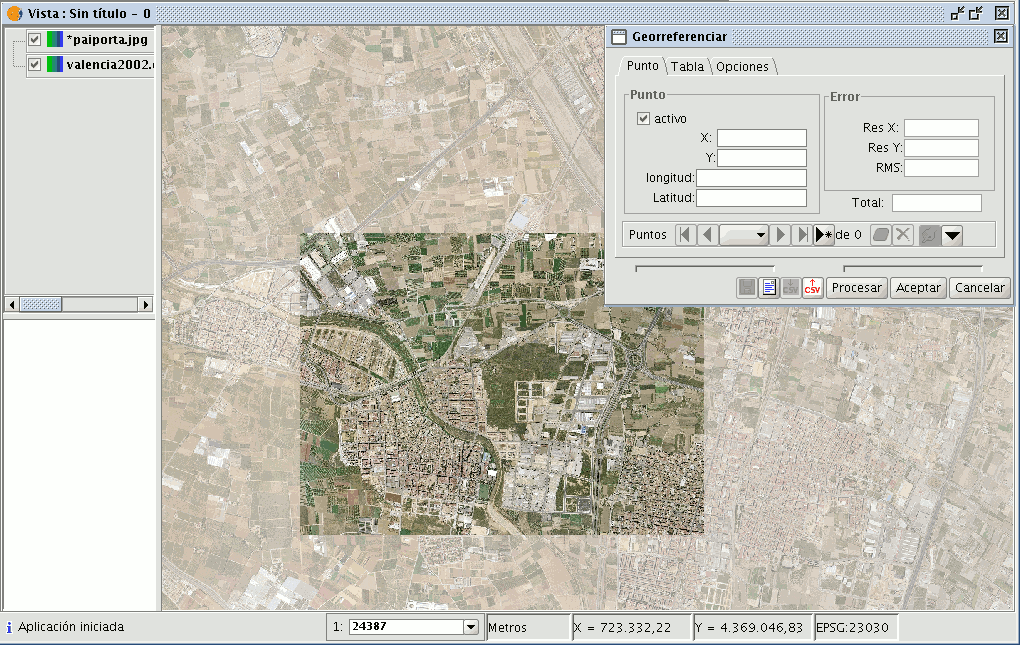
Click on the “New point” button in the “Georeference” dialogue and go to the view.

Place the mouse pointer over the image to be georeferenced and look for a control point. This point is defined as a red circle with a cross in the middle. If you move outside the boundaries of this image, gvSIG shows an error message and you will have to select a point once again. If you click on the following button

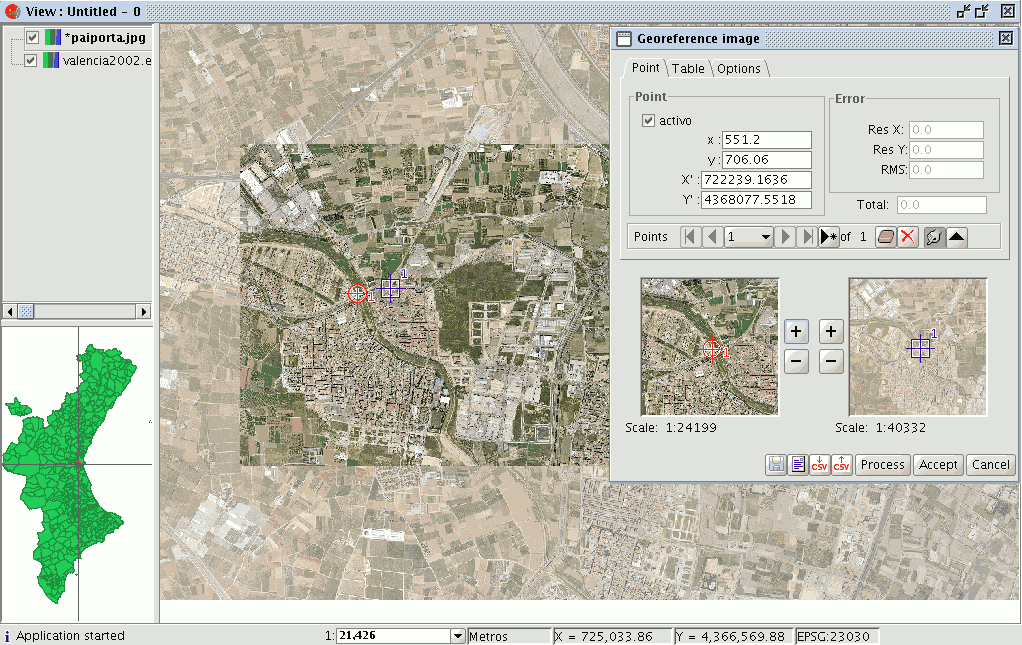
two small windows will drop down. In the left-hand window, the location of the created control point appears over an image zoom, as the following image shows.
If you wish to specify the point further, you can zoom into the image using the zoom tools in the centre of the dialogue box.

If you then click on the point in the mini view and drag it you can move its location.
These changes will automatically be reflected in the gvSIG view.
When you have marked the control point on the image to be georeferenced, this will disappear from the view (this option is marked by default in the "Options" tab in the "Georeference" window and can be modified at any time) and will only leave the base map with the destination point marked on the view.
In this case, the point is defined by a blue square with a cross in the centre.
You can do the same with the mini view on the right as you did with the left, i.e. if you wish to move closer to the point location, you can zoom into the right-hand image and drag the point over the view to place it more precisely.
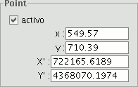
You can also specify the points in the text boxes in the georeference dialogue window. When the points have been input, press “Enter” and the point will be located in the view.
Remember that the “X” and “Y” text boxes belong to the image to be georeferenced and that “Longitude” and “Latitude” correspond to the georeferenced image. If you have made a mistake with the point and wish to delete it, click on “Remove selected point”.

If you click on this button, a confirmation message will appear.
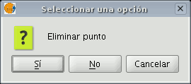
If you click on "Yes", the point will be deleted. If you wish to remove all the points, click on the “Remove all the points” button.

The control point selection must be repeated as a minimum of three points are required for georeferencing, although at least nine are advisable.
There is another series of tools in the “Georeference” window:

This tool allows you to go to the first control point, to the previous point, search for control points using a pull-down menu, go to the following control point and go to the last pull-down point respectively.
This button allows you to select control points from the view. Firstly, select the control point of the image to be georeferenced and finally, the control point of the destination coordinate.

You can disable an input control point via the "Active” check box in the “Point” tab. This means that the point will not be used in the error and georeference calculations and the symbols will not appear in the view. If you need the point again, you can enable the check box.
If you click on the “Table” tab, a table will appear with all the points and their errors. This table can be enlarged to show more information.
Guardar y cargar puntos de control
When you have finished the georeference process, you can save your control points by using the following tools:

In a metadata file associated with the image with the .rmf extension (if data already exists in this file, gvSIG will warn you that it is going to overwrite it).

In a .csv file: In this case, a dialogue window opens to select a file to save the data (X, Y coordinates and the errors in X, Y and RMS).

However, if you wish to add points from a file, use the following tools to retrieve .rmf control points associated with the image.

To load control points from a .csv file.
N.B.: You can also save the georeference points in the table panel.
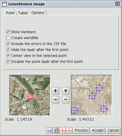
Opciones
You can use the “Options” tab in the georeference window to enable and disable some of the options according to your preferences.
Restricciones
It is currently only possible to georeference bmp, gif, jpg, png and tif formats.
Brillo y Contraste y Realce
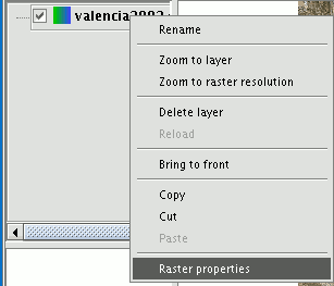
Applying “Brightness and Contrast” and “Enhance” filters to raster images. Firstly, load the cartography in raster format in a view and right click on the name of the raster layer selected in the ToC.
When the menu appears select the “Raster properties” option.
Then go the “Enhance” tab.
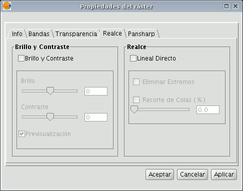
You will see that the “Brightness and contrast” and “Enhance” adjustment panels are disabled by default. These panels can be enabled by checking the boxes at the top of each panel.
If these check boxes are disabled no filters will be applied to the image even though the values have been input into the panel.
If, at any time, any of these filters have been applied to the image, the values will appear in the panel.
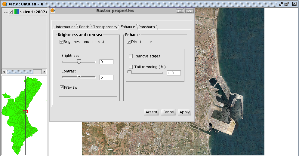
You will find two slider controls in the “Brightness and contrast” panel.
Values can be modified by using the slider or by directly inputting the values in the numerical field on the right and pressing “Enter”.
The brightness and contrast increase range goes from -255 to 255. To fine tune these values without having to input them in the numerical field, click one end of the slider control to either increase or decrease the value, unit by unit.
You will find a “Preview” check box in the panel. This is useful for obtaining a preview of the image without having to “Accept” or “Apply” changes every time they are made. If this check box is enabled, the image is refreshed with the new filters when the mouse button is released after modifying the brightness or contrast values using the slider control or when “Enter” is pressed if the numerical field has been used to modify the value.
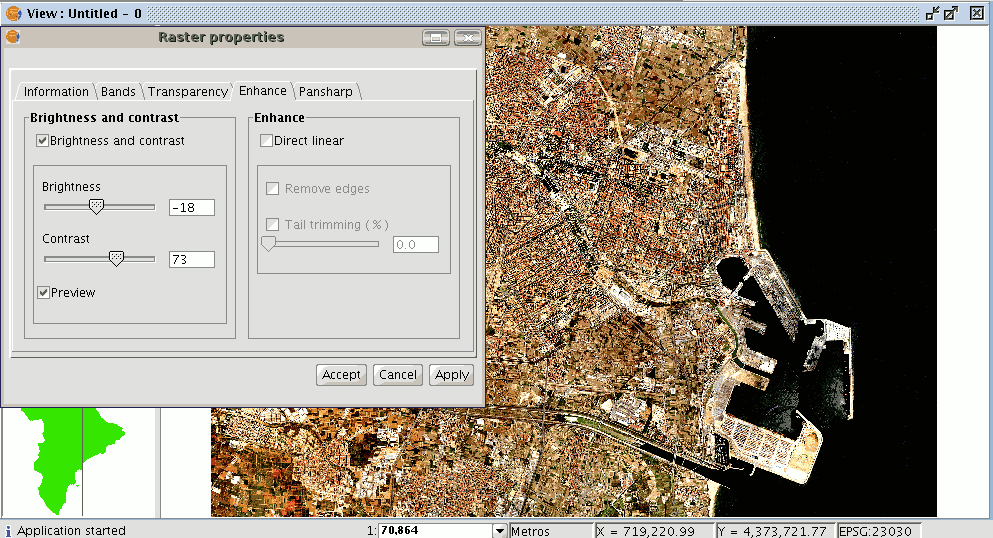
When brightness and contrast filters are applied the previous image takes on the above appearance.
When “Cancel” is pressed, no changes are applied and the input values are lost.
If you press “Accept” and you return to “Raster properties” you will see that the previously input values have been saved.
Transparencia por píxel
This assigns transparency to a raster based on the colour of its pixels. To assign this transparency, first load the cartography, then place the mouse pointer in the ToC over the raster layer you wish to modify. Right click and the contextual menu will appear.
Select the "Raster properties" option. When the dialogue box opens, select the "Transparency" tab. Only the top part of the panel corresponds to this tool. Enable the “Activate” check box and the controls that correspond to this function will be activated.
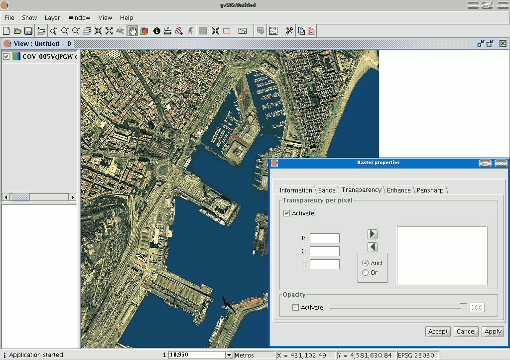
You can write the required combination of red, green and blue values in the “R”, “G” and “B” text boxes. When you have input these values, you can add them to the list with the right-facing arrow. These values will be added with an AND (&) if the “And” check box is enabled and with an OR (|) if the “Or” check box is selected.
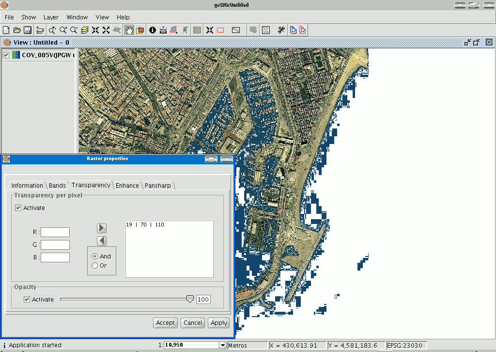
Adding the values with an AND means that all the pixels that have the red, green and blue values we have input will become transparent. Adding the values with an OR means that all the pixels that have the red or green or blue values we have input will become transparent. If you select an entry from the list and click on the left-facing arrow, the values will appear in the text boxes and can be modified.
You can input multiple values in the list. This means that when you accept the operation all the pixels whose colour coincides with the values input in the list will be transformed.
Seleccionar capas ráster
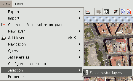
This tool allows you to select raster layers from the view and for them to be selected in the ToC. This is useful if you are using an orthophoto mosaic and you need to find out exactly which orthophoto you are working with. You can access this tool from the tool bar by clicking on the following button

or by going to the “View” menu then to “Selection”.
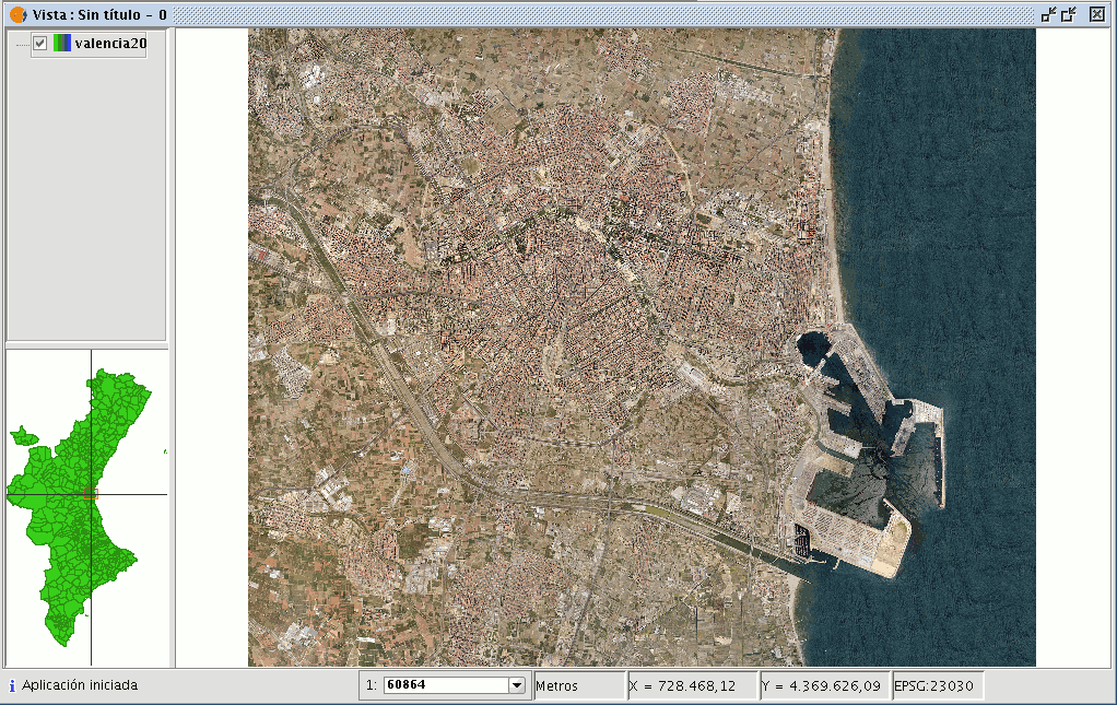
We are now going to show an example of the use of the tool. Remember that there are a large number of orthophotos in the ToC with similar names which as a whole make up the province of Valencia in the “View”.
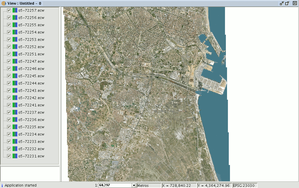
Go to the view. Make sure the selection tool for the raster layer is active and click on the orthophoto you wish to work with.
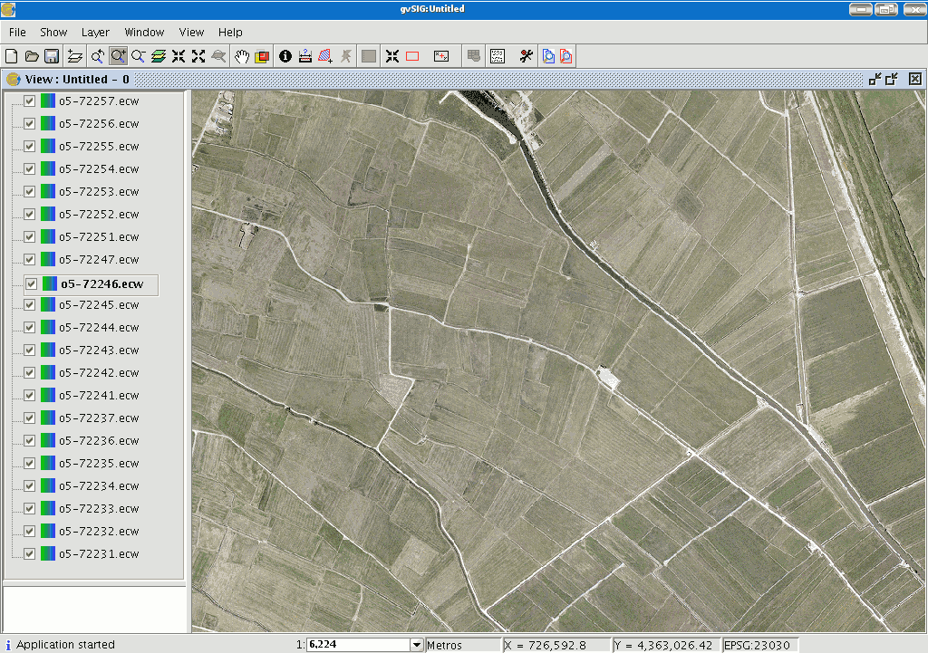
You will see that the chosen orthophoto has automatically been selected in the ToC.
